You can model applications using one of the following:
-
Tiers and Components
-
Services and Containers
You can use Change Tracking to track all the changes for non-runtime objects such as the application model, components, artifacts, resources, the environment model, and projects. See Change Tracking for more information.
When defining a component or container, you specify the artifact repository (plugin) and the artifact version that you want to use. CloudBees Flow supports artifacts from a variety of Artifact Repositories, such as the EC-Artifact repository, Maven based repositories such as Nexus (using EC-Nexus) or Artifactory (using EC-Maven), or artifacts on any file system (using EC-FileSysRepo). These artifacts could point to any build outputs, configuration scripts, database, scripts, and so on. The information that you enter in the component or container definition depends on the artifact repository that you select. For more information about artifacts, see Artifact Management and Artifacts .
Applications consist of services and the processes that orchestrate the deployment of these services. Each application object has one or more application services, where a service is a logical group of containers. A container is based on an artifact, and the container definition contains a reference to this artifact.
When using containers and services, you can:
-
Create services and containers under applications
-
Create clusters in environments (CloudBees Flow supports GCE and ECS)
-
Map services to clusters and set provider-specific values
Creating a New Application
Applications consist of components and the processes that orchestrate the deployment of these components. Each application object has one or more application tiers, where a tier is a logical group of components, and one or more services, where a service is a logical grouping of containers.
A component is based on an artifact, and the component definition contains a reference to this artifact.
This example shows how to create a “hybrid” application consisting of an application tier with a component and two services with a container in each service.
Authoring Component Processes
In a component process, you define a set of actions that will be executed on a specific component during the deployment. A component process step can be defined as a call to a CloudBees Flow plugin or procedure, a direct command or script in any scripting language, a manual task, or a utility function (a higher-order operation than a plugin).
In the Cleanup DB component of the DB application tier:
-
Click + to start authoring a component process. The New Component Process dialog box appears.
-
In the New Component Process dialog box, enter the following details:
-
Enter `updateDB ` in the Name field.
-
Enter an optional description in the Description field.
-
Keep the selection as Deploy in the Type field. This value determines track what is built, tested, and deployed during the application deployment. The default is Deploy.
-
Deploy –Enables Inventory Tracking. The CloudBees Flow server tracks artifacts deployed to environments.
-
Undeploy –After the first successful job step in a component process with this setting, the automation platform removes the environment inventory record.
-
Other –Disables Inventory Tracking.
-
-
Select a workspace.
-
Check Time limit as required. This allows you to configure a maximum amount of time that the step can execute; abort if it exceeds this time.
-
Add credentials as required. This allows the process to run in the context of the selected credential. See Attaching Credentials to Application and Component Processes for more information.
-
-
Click OK.
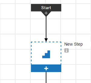
The Component Process Visual Editor opens.
The process model shows a process with Start and Finish steps with a New Step in between them.
-
Click + in the first step.
-
Define the first step in the Component Process Step dialog box:
-
Enter `getScript ` in the Name field.
-
Enter
Retrieve the new sql filein the Description field. -
Use the Continue on Error setting in the On Error field. Go here for more information.
-
Use the all setting in the Run if field. Go here for more information.
-
Select a workspace.
-
Check Time limit as required. This allows you to configure a maximum amount of time that the step can execute; abort if it exceeds this time.
-
Check Time limit as required. This allows you to configure a maximum amount of time that the step can execute; abort if it exceeds this time.
-
Click Next.
-
-
Define the first step in the Step Type dialog box based on a component operation, select Component Operations as the Step Type. The parameters for this process step are automatically inherited from the "update.sql" component.
-
Click OK.
-
Click + on the bottom of the first step to add a new step below it.
-
Click + in the second step.
-
Define the second step in the Component Process Step dialog box:
-
Define the second step in the Component Process Step dialog box based on a component operation by selecting Procedure as the Step Type. The parameters for this process step are automatically inherited from the "update.sql" component.
-
Click OK.
This is the resulting component process:
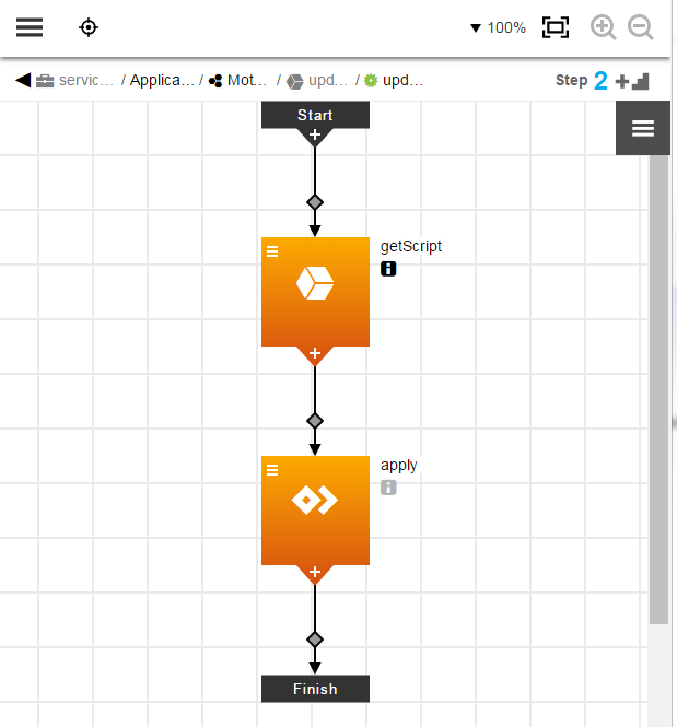
-
You can get details about each step by clicking i under the step name.
-
The first step is a component operation.
The second step is a procedure.
-
These steps are deployed in series.
The second step can only start after the first step is completed.
-
Clicking
 displays menu where you can select options:
-
Details –View step details
-
Properties –View step properties.
-
Access Control –View access control settings.
-
Add Connector –Add another connector to the step.
-
Track Changes –View the Change History.
-
Authoring a New Application Using Services and Containers
-
Define an application service and the containers in it.
A new service named Service1 appears.
In the Service 1 tile, click
and select Details to edit the details in the Container Definition dialog box.-
Rename the application service to
store-front-endand click OK. -
-
Click + under the Containers in the hierarchy menu.
-
Click Create New.
-
Enter
Configas the container name, and click Next. The Container Definition dialog box appears. -
Click the expander arrows to fully expand the dialog box for each section.
-
Enter the container attributes as needed. The following table describes the available attributes.
-
-
| Label | Description | Default |
|---|---|---|
Details |
||
Registry |
Public: Specifies that your container images are stored in a public Docker registry. Private: Specifies that your container images are stored in registries other than a public Docker registry. |
Public |
URL |
(Optional) Private container registry URL. This is the registry where your image is stored. For example, |
– |
Credential |
(Optional) Credentials (username and password) required to access the private registry. You must create a credential under a project and attach to it ( by providing the absolute path when using ectool or by browsing and selecting it in the UI). |
– |
Image |
Relative or absolute path to the container image. For example, |
– |
Version |
(Optional) Version of the image. For example, |
|
Minimum CPU Requested |
(Optional) Amount of CPU (in number of cores) requested by the container. Specifying the amount of CPU needed allows the underlying container service to make better placement decisions when deploying the services on the nodes in the cluster based on the available capacity. If no value is specified, the underlying container service determines the default. |
– |
Maximum CPU Allowed |
(Optional) Maximum amount of CPU (in number of cores) that the container may use. If the limit is exceeded, the behavior depends on the container service. |
If this is left empty, the platform-specific default is used. |
Memory |
(Optional) Amount of memory (in MB) requested by the container. Specifying the amount of memory needed by the container allows the underlying container service to make better decisions when deploying the services on the nodes in the cluster based on the nodes' available capacity. If no value is specified, the underlying container service determines the default. |
None. However, on ECS, the plugin will use a default soft memory limit (memory request) of 128 MB. |
Memory Limit |
(Optional) Maximum amount of memory (in MB) that the container may use. If the limit is exceeded, the behavior depends on the container service. |
If this is left empty, the platform-specific default is used. |
Volume Mounts |
(Optional) Volume mounts required by the container. Use JSON format. For example:
|
– |
Command |
(Optional) Comma-separated command arguments to use with the container’s entry point. If specified, they override the |
– |
Entry Point |
(Optional) Comma-separated list of one or more values to override the For details about how |
– |
Environment |
||
Variable |
( Optional ) Environment variable name used in the container. For example, |
– |
Value |
( Optional ) Default value for the environment variable. You can override these values during the service-to-cluster mapping phase. |
– |
Ports |
||
Name |
( Optional ) Logical name for the container port. For example, |
– |
Container Port |
( Optional ) Port that the container is listening on. |
– |
-
Click OK.
-
Click the
 button to add a service named store-backend as described above and enter the container attributes as needed.
-
Authoring Application Processes
At the application (parent) level, you author application processes. When deploying an application, the application process that you select is executed to orchestrate operations against the application. An application process step can be defined as a call to a CloudBees Flow plugin, procedure, or component process as well as a direct command, script, a manual task, or a utility function (a higher-order operation than a plugin).
Property Picker
The Property Picker is available from application processes to make it easy to create custom deployments. It includes properties set on the project.
-
The Property Picker contains a pull-down menu to let you select project or related object properties.
-
The Property Picker lets you select built-in or custom properties or parameters in process step conditions that you need to reference without remembering and writing out property names and paths.
In the Application Editor for the Upgrade application:
-
Click + in the Application Processes section of the left hand hierarchy to start authoring an application component process.
-
In the New Application Process dialog box, enter the following details:
-
Enter
deployin the Name field. -
Enter an optional description in the Description field.
-
Select a workspace.
-
Check Exclusive access to require exclusive access to the environment. At runtime, if the environment is not available, the process waits until it becomes so and then locks it for use from other processes. See Environment Locking for details.
-
Check Time limit as required. This allows you to configure a maximum amount of time that the step can execute; abort if it exceeds this time.
-
Add credentials as required. This allows the process to run in the context of the selected credential. See Attaching Credentials to Application and Component Processes for more information.
-
-
Click OK.
The Application Process Visual Editor opens. The process model shows a process with Start and Finish steps with a New Step in between them.
Clicking i under the step name displays the details about the process step.
Example:
+
-
Click + in the first step.
-
Define the first step in the Application Process Step dialog box :
-
Enter
applyDBChangein the Name field. -
Use the Stop on Error setting in the On Error field. Go to Application Deployment Options for more information.
-
Use the all setting in the Run if field. Go here for more information.
-
Select the workspace and time limit.
-
Click Next. The Step Type dialog box appears:
-
-
Define the second step in the Application Process Step dialog box based on a service by clicking Component > update.sql > updateDB. The step is defined by the component Deploy process for the update.sql component:
-
Click OK.
-
Click + on the bottom of the first step to add a new step below it.
-
Click + in the second step.
-
Define the second step in the Application Process Step dialog box as follows:
-
Define the second step in the Application Process Step dialog box based on a service by selecting Service > store-backend. The step is defined by the component Deploy process for the motorbikeMS service.
-
Click OK.
This is the application process called deploy:
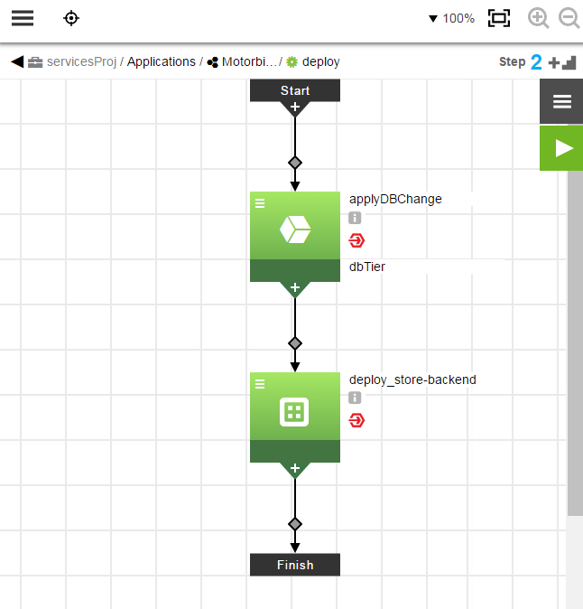
-
You can get details about each step by clicking under the step name.
-
Clicking
displays a menu where you can select the following options:-
Details –View step details
-
Properties –View step properties.
-
Access Control –View access control settings.
-
Add Connector –Add another connector to the step.
-
Track Changes –View the Change History.
-
Creating Environments
Environments are logical grouping of machines to which various applications can be mapped and deployed. Using environments and templates, you can model the infrastructure and the middleware available for various applications. Environments consist of logical groups of resources with a similar function or role called environment tiers. An environment tier can be a group of machines with a similar function or role, such all the web servers or application servers or database servers for an environment. Resources are actual target end point machines (such as physical servers), virtual machines, or mobile devices.
Environments can be static, dynamic, or hybrid. A static environment has resources that are already provisioned and managed at the platform level. Each resource has its own logical name to identify it from the other resources in the system. It also can be assigned to one or more resource pools or to a zone (a collection of agents). Several resources can correspond to the same physical host or agent machine. Resources can also be configured as standard or proxy . Standard resources are machines running the CloudBees Flow agent on a supported agent platform while proxy resources (agents and targets) are on remote platforms or hosts that exist in your environment and requires SSH keys for authentication. The CloudBees Flow agent does not need to run on the remote platform or host. See Configuring Resources for more information about to create, configure, and manage resources.
This example shows to how model a static environment to which the application will be deployed. For information about dynamic environments and how to model them, see xref:model-app-dyna.adoc[Deploying Applications in Dynamic Environments] .
Creating Environment Tiers
In the Environments List:
-
Click Add + to add an environment.
-
The Environment dialog box appears.
-
Enter
A—Amazon ECS Productioninto the Name field. -
Select a project to which the new environment will belong in the field and enter a description of the environment.
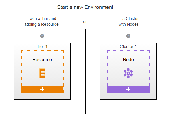
You can include hyperlinks as part of an object description for any CloudBees Flow object. This dialog box lets you quickly define an environment tier and the resources in it or a service and the nodes in it.
-
Click OK.
The Environment Editor opens.
-
Click Tier 1.
-
Define an environment tier and assign resources it.
-
In the New dialog box, click Add resources.
-
Click
, then click Details, then rename the environment tier to "mysql," and then click OK. -
To define the resource:
-
Click + under the Resource.
-
Click Add resources.
-
Select the resource that you want to assign to the environment tier, and click. A resource is available if it is enabled.
The Environment Editor now has an environment tier called
mysqlwith one resource. Example: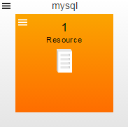
-
-
Creating Environment Clusters
-
Click + at the bottom of Cluster 1. The Cluster Definition dialog box appears:
-
In the Cluster Definition dialog box, select a platform. For example, Amazon EC2 Container Service.
-
Enter the cluster attributes as needed. The following table describes the available attributes.
Description Default Configuration Configuration
Name of an existing configuration which holds the connection information for Amazon ECS.
Container Cluster Name
Name of the cluster to be provisioned for in Amazon ECS.
Description
(Optional) Description of the cluster that needs to be provisioned.
–
Desired Capacity
Number of EC2 instances that should be running in the group.
Maximum Size
(Optional) Maximum size of the group.
Minimum Size
(Optional) Minimum size of the group.
VPC Subnet Ids
(Optional) Comma-separated list of subnet identifiers for your virtual private cloud (VPC) in which to launch the EC2 instances.
Availability Zones
Availability zones in which to launch your EC2 instances.
Image
ID of the Amazon Machine Image (AMI) to use to launch your EC2 instances.
Instance Type
Instance type of the EC2 instance.
Security Groups
One or more security groups with which to associate the instances.
Key Name
(Optional) Name of the key pair.
Associate Public IP
(Optional) Checkbox that specifies whether to associate a public IP address.
Container Instance IAM Role
ECS container instance IAM role for the launched container instances to use.
Results Property Sheet
Name of the property sheet to hold results.
-
Click OK.
-
In the cluster that you just created, click
 > Details. The Environment Cluster dialog box appears:
 -
In the Environment Cluster dialog box, enter a cluster name into the Name field. For example,
ecs-cluster1. -
Click OK.
Defining Tier Maps and Cluster Maps
Before deploying application that use an application tier or an application cluster, you must define a tier map to associate the application with an environment.
Defining an Application Tier Map
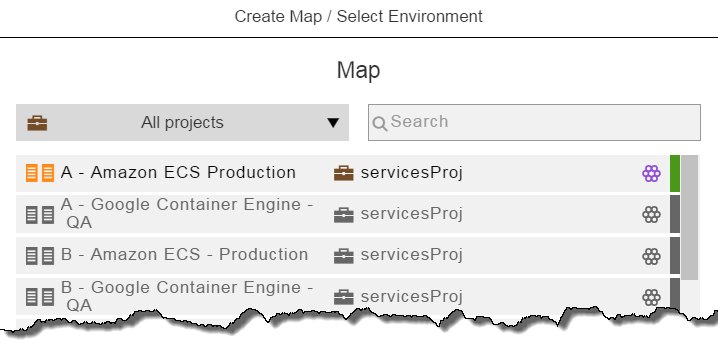
In the Application Editor for the application that you want to deploy:
-
Click Environment.
-
Example: Select Amazon ECS Production.
-
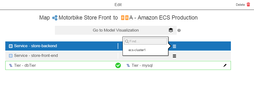
Map the application tier to the environment tier:
-
In the application tier, click
 in the corresponding environment tiers column and select an environment tier. Select one from the list or enter the search criteria in the Search field.
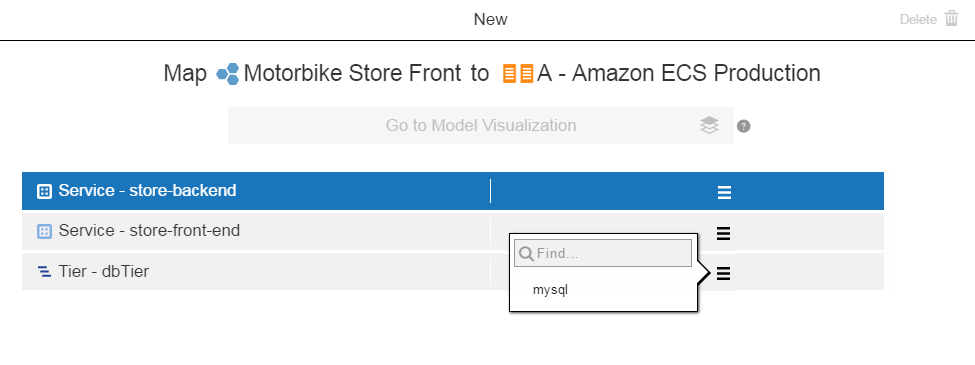
-
Click OK when the application tier is mapped to an environment tier.
-
Defining an Application Cluster Map
You can override the service and container attributes and add platform-specific service and container attributes.
-
Map the store-backend to an environment tier:
-
In the service, click
in the corresponding environment tiers column and select an environment tier. Select one from the list or enter the search criteria in the field.Example:
-
Click OK when the application tier is mapped to an environment tier.
-
-
Map the store-front-end service to an environment tier as described above.
The application now has one tier map and two cluster maps.
-
Click
 to configure the cluster map for the store-backend service.
 -
Enter the cluster map attributes as needed. The following table describes the available attributes.
Label Description Default Service Configuration Details
You can use these fields to override the service and container attributes and add platform-specific service and container attributes.
Volume
(Optional) Volume pointing to a storage device or a partition that can be mounted by a container. Use JSON format. For example:
[{""name"": ""web-content"",""hostPath"": ""/var/html"" Location on host/container instance where volume is expected to be already attached.}]–
Number of Service instances
(Optional) Number of service instances to use.
1
Rolling Deployment—Min Service Instances
(Optional) Minimum number of services that can be brought down during a rolling deployment.
If this is left empty, the platform-specific default is used.
Rolling Deployment—Max Service Instances
(Optional) Maximum number of services that can be created during a rolling deployment.
If this is left empty, the platform-specific default is used.
Port Mapping
Name
Reference to the container port name.
–
Container Port
Reference to the container port.
–
Listener Port
External or listener port mapping for the container port. A listener port setup is required for pods to communicate with each other.
–
Amazon EC2 Container Service Specifications
LoadBalancer Name
Name of the load balancer on Amazon EC2. Required if the service contains port mappings.
–
IAM role for Service and Loadbalancer
Name or full Amazon Resource Name (ARN) of the AWS Identity and Access Management (IAM) role that allows ECS to make calls to your load balancer on your behalf.
–
-
Click
to configure the cluster map for the store-front-end service as described above.
Deploying and Troubleshooting Applications
This example shows how to deploy the application multiple times with different runtime conditions.
First Run
In the Applications List, clicking ![]() and selecting New Run opens the dialog box where you can set the runtime settings.
and selecting New Run opens the dialog box where you can set the runtime settings.
-
In the Select Process field, select Run.
-
In the Select Environment field, select QA.
-
You can select a snapshot in the Select a Snapshot field if you have one or more.
-
For the first run, all artifacts will be deployed.
-
Smart Deploy and Stage Artifacts are enabled.
Click OK to start the application run.
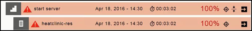
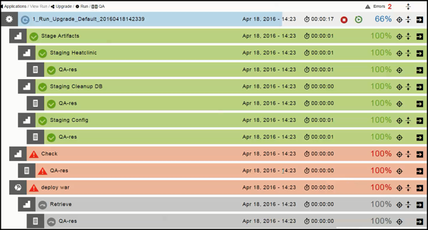
The Applications View Run page shows the progress of the application run:
-
The blue steps are running (in progress).
-
The green steps were completed successfully.
-
The red steps failed.
Clicking
 opens the Job Details page where you can begin the troubleshoot the step.
 -
The gray steps were skipped.
Environment Locking
CloudBees Flow allows simultaneous application and microservice deployments to the same environment. These deployments can be for the same or different applications or microservices. This can lead to deployment failures when deployment steps are working on the same resources, for examples modifying the same files or starting and stopping the same application server.
Environment locking for exclusive access restricts simultaneous deployments configured for the same environment. It allows application or microservice to exclusively lock an environment for a deployment. When an environment is locked, all other deployments that are started after the lock is acquired are queued.
Exclusive environment access is configured on application processes, top-level microservices, or both at object create/edit time. See information about setting exclusive access in Authoring Application Processes. At runtime, CloudBees Flow checks environment availability:
-
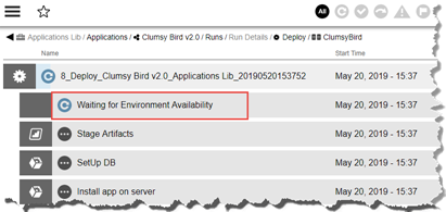
If there is a ongoing reservation or active blackout period on the environment CloudBees Flow inserts Waiting for Environment Reservation as the first step in the deployment job. Once the reservation or blackout ends and the process requires exclusive access but the environment is not available, users notice Waiting for Environment Reservation step is renamed to Waiting for Environment Availability.
-
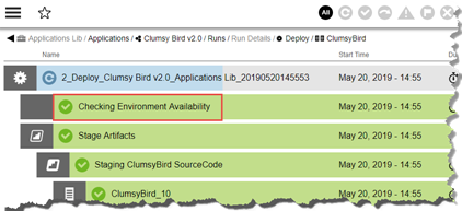
Otherwise, Flow inserts Checking Environment Availability as the first step in the deployment job. If the process requires exclusive access but the environment is not available this step is renamed Waiting for Environment Availability.
-
When using rolling deploy, Checking Environment Availability is inserted only once regardless of the number of phases or batches.
|
|
Subsequent Runs
After the first application run, you can deploy the Run process to the QA environment with other deployment options.
Based on the Last Run
Clicking ![]() and selecting Last Run opens the dialog box where you can set the runtime settings. It displays the runtime settings from the previous. You can deploy the application using the same settings as the previous run or you can modify one or more them for the current run.
and selecting Last Run opens the dialog box where you can set the runtime settings. It displays the runtime settings from the previous. You can deploy the application using the same settings as the previous run or you can modify one or more them for the current run.
Based on Schedules
Clicking ![]() and selecting Schedule opens the list of schedules for the application. If there are no schedules, click *There are no Run Schedules to add one.
and selecting Schedule opens the list of schedules for the application. If there are no schedules, click *There are no Run Schedules to add one.
-
Select Create new to create a new schedule, and then enter the schedule details .
-
Select from Previous Runs to create a schedule based on a previous application run.
A list of the last five application runs appears.
Select an application run, and then enter the schedule details .
-
In the Schedule name field, enter the schedule name.
-
In the Frequency field field, click the down arrow and select Once, Daily, Weekly, or Monthly.
-
In the Country field, click the down arrow and select a value in the drop-down list.
-
In the City field, click the down arrow and select a value in the drop-down list.
-
In the Start field, click
 if you want to change the start date, and click in the hh:mm box to set the start time using the 24-hour clock.
 -
In the End field, click
and select the end date from the pop-up calendar. The end time is the same as the start time. -
Click Next.
The dialog box where you can set the runtime settings appears. You can also modify the runtime settings at this time.
-
Click OK. A configuration message is displayed with the deployment run time.
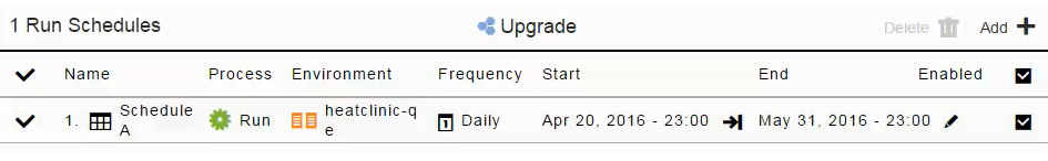
When you view the list of schedules for the application again, the schedule that you created appears in the list.
Runtime Settings
In the dialog box where you can set the runtime settings, the Artifacts field looks like this for a full run:

-
Partial deploy with smart deploy and artifact staging are enabled:
Clicking
opens the list of artifacts and containers that can be deployed in the application process. Artifacts are grouped by application tier. You can enable or disable an artifact within a tier or the entire tier itself as part of a deployment.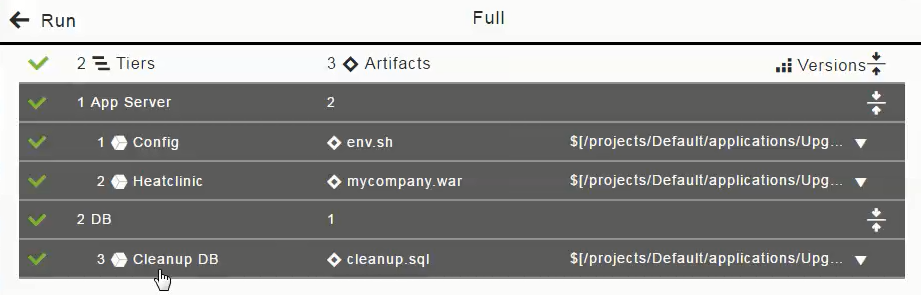
If you want to only deploy the DB artifact (cleanup.sql), click in the "1 App Server" column to deselect (disable the selection of) the Config and Heatclinic components (based on the
env.shand ` mycompany.war` artifacts), and click OK.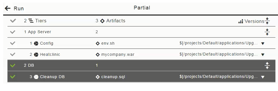
The Artifacts field now looks like this for a partial run:

With microservices and containers, you can enable or disable a service:
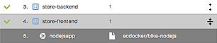
(You cannot disable an individual container within a service.)
-
Partial deploy with specific artifact versions and with smart deploy and artifact staging are enabled:
In the list of artifacts to be deployed in the application process, click in the "2 DB" row to deselect the "Cleanup DB" component (based on the
cleanup.sql ` artifact), select the Latest version of the `mycompany.warartifact, and click OK.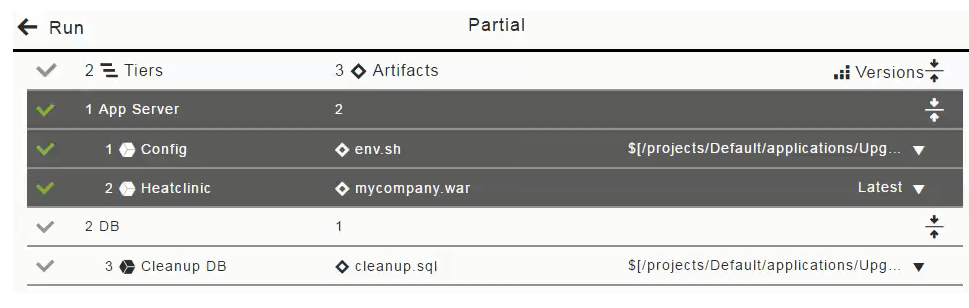
The Artifacts field now looks like this for the partial run:

-
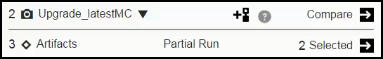
Snapshot with partial deploy and with smart deploy and artifact staging are enabled. In the Select a Snapshot field, click the down arrow and select the Upgrade_latestMC snapshot.
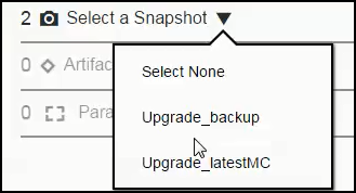
In the list of artifacts to be deployed in the application process, click in the "1 Config" row to deselect (disable the selection of) the Config component (based on the
env.shartifact) and click OK.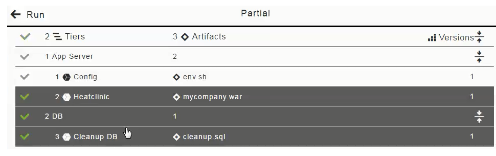
The Select a Snapshot and Artifacts fields now look like this for the partial run:
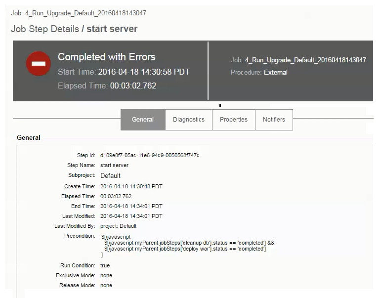
Viewing the Real-Time Progress of Deployments
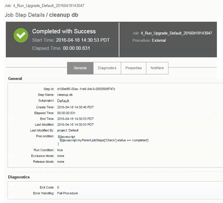
This example shows the job details for a specific step. Clicking ![]() in the cleanup db step opens the Job Details page:
in the cleanup db step opens the Job Details page:
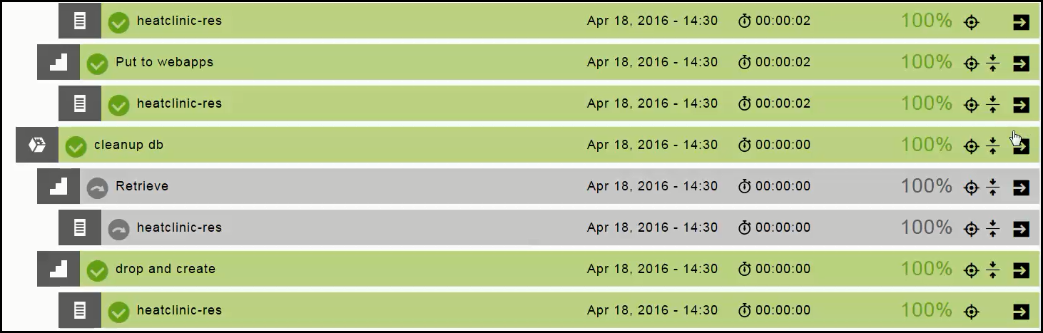
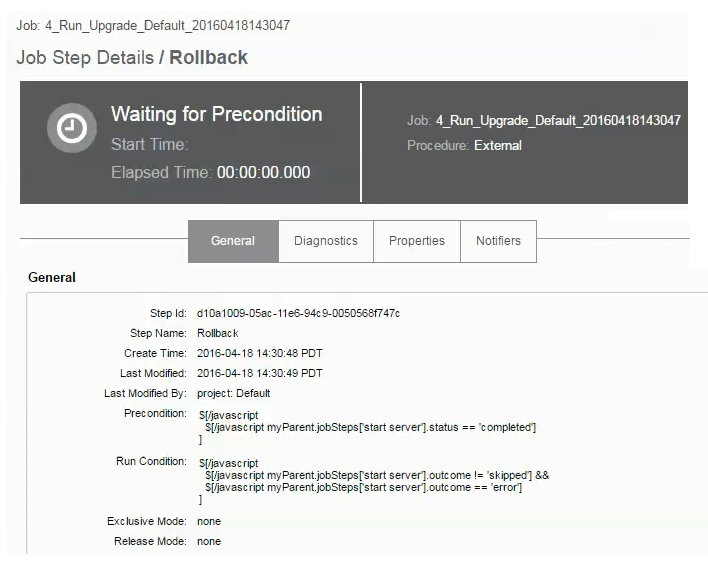
This example shows that the rollback step has not run yet:

Clicking ![]() in the rollback step opens the Job Details page, showing that the status is Waiting for Precondition . This step will not run until the precondition is met.
in the rollback step opens the Job Details page, showing that the status is Waiting for Precondition . This step will not run until the precondition is met.