This document is designed to help you ensure that your Amazon Web Services (AWS) Kubernetes cluster is optimally configured for running CloudBees CI in a secure and efficient way.
These are not requirements, and they do not replace the official Kubernetes and cloud provider documentation. They are recommendations based on experience running CloudBees CI on Kubernetes. Use them as guidelines for your deployment.
For more information on Kubernetes, refer to the Kubernetes documentation.
Terms and definitions
- Jenkins
-
Jenkins is an open-source automation server. With Jenkins, organizations can accelerate the software development process by automating it. Jenkins manages and controls software delivery processes throughout the entire lifecycle, including build, document, test, package, stage, deployment, static code analysis and much more. You can find more information about Jenkins and CloudBees contributions on the CloudBees site.
- CloudBees CI
-
With CloudBees CI, organizations can embrace rather than replace their existing DevOps toolchains while scaling Jenkins to deliver enterprise-wide secure and compliant software.
- Operations center
-
Operations console for Jenkins that allows you to manage multiple Jenkins controllers.
Architectural overview
This section provides a high-level architectural overview of CloudBees CI, designed to help you understand how CloudBees CI works, how it integrates with Kubernetes, its network architecture and how managed controllers and build agents are provisioned.
CloudBees CI is essentially a set of Docker containers that can be deployed to run a cluster of machines within the Kubernetes container management system. Customers are expected to provision and configure their Kubernetes system before installing CloudBees CI.
CloudBees CI includes the operations center that provisions and manages CloudBees managed controllers and team controllers. CloudBees CI also enables managed controllers and team controllers to perform dynamic provisioning of build agents via Kubernetes.
Machines and roles
CloudBees CI is designed to run in a Kubernetes cluster. For the purposes of this section, a Kubernetes cluster is a set of machines (virtual or bare-metal) that run Kubernetes. Some of these machines provide the Kubernetes control plane. They control the containers that run on the other type of machines known as Kubernetes Nodes. The CloudBees CI containers will run on the Kubernetes Nodes.
The Kubernetes control planes provide an HTTP-based API that can be used to manage the cluster, configure it, deploy containers, and so on. kubectl is a command-line client that can be used to interact with Kubernetes via this API. For more information on Kubernetes, refer to the Kubernetes documentation.
CloudBees CI Docker containers
The Docker containers in CloudBees CI are:
-
cloudbees-cloud-core-oc: operations center -
cloudbees-core-mm: CloudBees CI managed controller
The Docker containers used as Jenkins build agents are specified on a per-Pipeline basis and are not included in CloudBees CI. For more details, refer to the example Pipeline in Agent provisioning.
The cloudbees-cloud-core-oc, cloudbees-core-mm, and build agent container images can be pulled from the public Docker Hub repository or from a private Docker Registry that you deploy and manage.
If you need to use a private registry, you have to configure your Kubernetes cluster to do that.
CloudBees CI Kubernetes resources
Kubernetes terminology
The following terms are useful to understand. This is not a comprehensive list. For full details on these and other terms, refer to the Kubernetes documentation.
- Pod
-
A set of containers that share storage volumes and a network interface.
- ServiceAccount
-
Defines an account for accessing the Kubernetes API.
- Role
-
Defines a set of permission rules for access to the Kubernetes APIs.
- RoleBinding
-
Binds a
ServiceAccountto a role. - ConfigMap
-
A directory of configuration files available on all Kubernetes nodes.
- StatefulSet
-
Managing deployment and scaling of a set of pods.
- Service
-
Provides access to a set of pods at one or more TCP ports.
- Ingress
-
Uses the hostname and path of an incoming request to map the request to a specific service.
CloudBees CI Kubernetes resources
CloudBees CI defines the following Kubernetes resources:
| Resource type | Resource value | Definition |
|---|---|---|
ServiceAccount |
|
Account used to manage Jenkins build agents. |
ServiceAccount |
|
Account used by operations center to manage managed controllers. |
Role |
|
Defines permissions needed by operations center to manage Jenkins controllers. |
RoleBinding |
|
Binds the operations center ServiceAccount to the |
RoleBinding |
|
Binds the jenkins ServiceAccount to the |
ConfigMap |
|
Defines the configuration used to start the |
ConfigMap |
|
Defines |
ConfigMap |
|
Defines the Bash script that starts the Jenkins agent within a build agent container. (Deprecated. For migration information, refer to Migrate from |
StatefulSet |
|
Defines a pod for the |
Service |
|
Defines a Service front-end for the |
Ingress |
|
Maps requests for the CloudBees CI hostname and the path |
Ingress |
|
Maps requests for the CloudBees CI hostname to the path |
Setting pod resource limits
You can specify default limits in Kubernetes namespaces. These default limits constrain the amount of CPU or memory a given pod can use unless the pod’s configuration explicitly overrides the defaults.
For example, the following configuration limits requests running in the master-0 namespace to 256 MB of memory and total memory usage to 512 MB:
apiVersion: v1 kind: LimitRange metadata: name: mem-limit-range namespace: master-0 spec: limits: - default: memory: 512Mi defaultRequest: memory: 256Mi type: Container
Overriding default pod resource limits
To override the default configuration on a pod-by-pod basis, configure the controller that needs more resources:
-
Sign in to the operations center.
-
Navigate to .
-
Select Add a pod template.
-
Locate the template you want to edit.
-
If the template you want to edit does not exist, create it.
-
-
On the Containers tab, select Add Containers and select container.
-
Select Advanced, and then modify the resource constraints for the template.
Visualizing CloudBees CI architecture
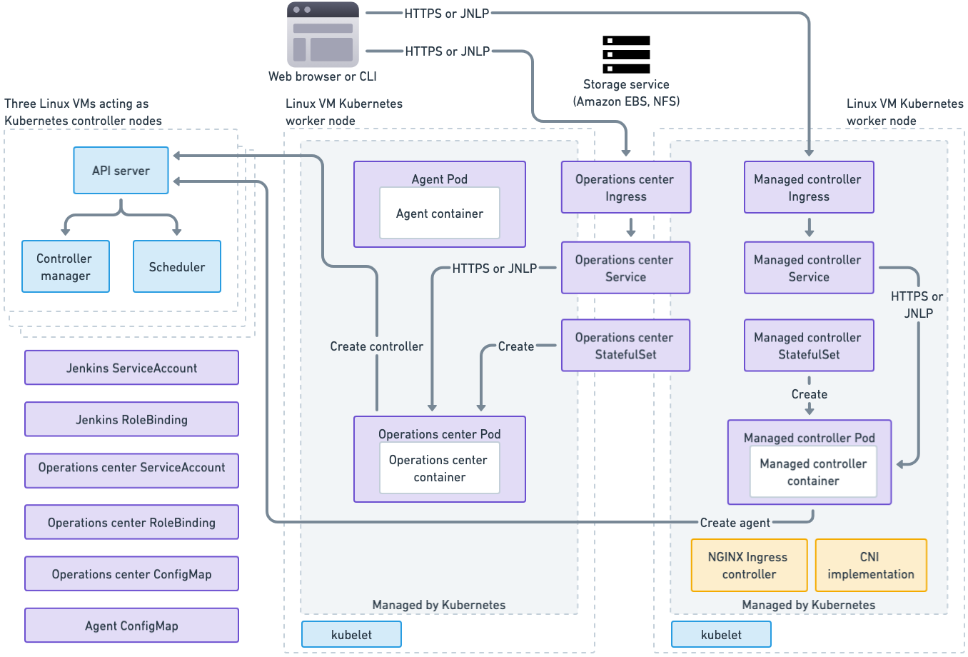
The diagram below illustrates the CloudBees CI architecture on Kubernetes. The diagram shows three Kubernetes control planes, which are represented by the three dotted-line overlapping rectangles on the left. The diagram also shows two Kubernetes worker nodes, which are represented by the two dotted-line large rectangles in the center and on the right.
Here are the key for the colors used in the diagram:
-
Blue: Processes that are part of Kubernetes
-
Purple: Kubernetes resources created by installing and running CloudBees CI
-
Yellow: Kubernetes resources required by CloudBees CI
Kubernetes control plane
Running on each Kubernetes control plane, there are the Kubernetes processes that manage the cluster: the API Server, the controller manager and the scheduler. In the bottom left of the diagram are resources that are created as part of the CloudBees CI installation, but that are not really tied to any one node in the system.
Kubernetes nodes
On the Kubernetes nodes and shown in green above is the kubelet process, which is part of Kubernetes and is responsible for communicating with the Kubernetes API server and starting and stopping Kubernetes pods on the node.
On one node, you see the operations center pod, which includes a Controller Provisioning plugin that is responsible for starting new controller pods. On the other node you see a controller pod, which includes the Jenkins Kubernetes Plugin and uses that plugin to manage Jenkins build agents.
Each operations center and controller pod has a Kubernetes Persistent Volume Claim where it stores its Jenkins Home directory. Each Persistent Volume Claim is backed by a storage service, such as an EBS volume on AWS or an NFS drive in an OpenShift environment. When a controller pod is moved to a new node, its storage volume must be detached from its old node and then attached to the pod’s new node.
Pod scheduling best practice
Prevent operations center and managed controllers pods from being moved during scale down operations by adding the annotation
cluster-autoscaler.kubernetes.io/safe-to-evict: "false"
apiVersion: apps/v1 kind: StatefulSet spec: template: metadata: annotations: cluster-autoscaler.kubernetes.io/safe-to-evict: "false"`
Managed controller provisioning
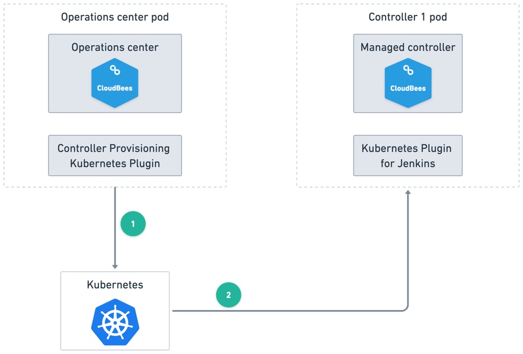
One of the benefits of CloudBees CI is the easy provisioning of new Jenkins managed controllers from the operations center UI. This feature is provided by the Controller Provisioning Kubernetes plugin. When you provision a new controller, you must specify the amount of memory and CPU to be allocated to the new controller, and then the plugin calls the Kubernetes API to create a controller.
The diagram below displays the result of a new controller launched via the operations center. The operations center’s Controller Provisioning Kubernetes plugin calls Kubernetes to provision a new StatefulSet to run the managed controller pod.
Agent provisioning
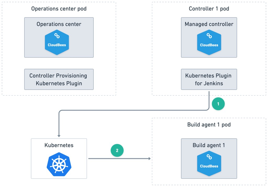
Agents are created and destroyed in CloudBees CI by the Kubernetes Plugin for Jenkins. A Jenkins Pipeline can specify the build agent using the standard Pipeline syntax. For example, below is a CloudBees CI Pipeline that builds and tests a Java project from a GitHub repository using a Maven and Java Docker image:
Pipeline example:
podTemplate(label: 'kubernetes', containers: [ containerTemplate(name: 'maven', image: 'maven:3.5.2-jdk-8-alpine', ttyEnabled: true, command: 'cat') ]) { stage('Preparation') { node("kubernetes") { container("maven") { git 'https://github.com/jglick/simple-maven-project-with-tests.git' sh "mvn -Dmaven.test.failure.ignore clean package" junit '**/target/surefire-reports/TEST-*.xml' archive 'target/*.jar' } } } }
In the above example, the build agent container image is maven:3.5.2-jdk-8-alpine.
It will be pulled from the Docker Registry configured for the Kubernetes cluster.
The diagram below shows how build agent provisioning works. When the Pipeline runs, the Kubernetes Plugin for Jenkins on the managed controller calls Kubernetes to provision a new pod to run the build agent container. Then, Kubernetes launches the build agent pod to execute the Pipeline.
CloudBees CI required ports
CloudBees CI requires the following open ports. Refer to the Kubernetes documentation for its port requirements.
| Port number | Description |
|---|---|
80 |
HTTP access to the web interface of operations center and managed controllers. |
443 |
HTTPS access to the web interface of operations center and managed controllers |
50000 |
TCP port for inbound agents access for direct connection between operations center and managed controllers, controllers, and agents. |
Network encryption
Network communication between Kubernetes clients such as kubectl, Kubernetes control planes, and nodes are encrypted via TLS protocol. Kubernetes Managing TLS in a Cluster explains how certificates are obtained and managed by a cluster.
Communication between application containers running on a Kubernetes cluster, such as the operations center and managed controllers, can be encrypted as well, but this requires the deployment of a network overlay technology.
End-to-end web browser to CloudBees CI communications can be TLS encrypted by configuring the Kubernetes Ingress that provides access to CloudBees CI to be the termination point for SSL. Network overlay and SSL termination configuration is covered in a separate section.
High Availability
Kubernetes can be configured for High Availability (HA) by using at least three Kubernetes control planes on three separate machines in different availability zones.
Persistence
Operations center and managed controllers store their data in a file-system directory, known as $JENKINS_HOME. The operations center has its own $JENKINS_HOME, and each controller also has one.
CloudBees CI uses a Kubernetes feature known as Persistent Volume Claims to dynamically provision persistent storage for the operations center, each managed controller, and build agents.
Cluster sizing and scaling
This document provides general recommendations about sizing and scaling a Kubernetes cluster for CloudBees CI starting with some general notes about minimum requirements and ending with a table of more concrete sizing guidelines recommended by CloudBees.
General notes
When sizing and scaling a cluster you should consider the operational characteristics of Jenkins. The relevant ones are:
-
Jenkins controllers are memory and disk IOPS bound, with some CPU requirements as well. Low IOPS results into longer startup times and worse general performance. Low memory results into slow response time.
-
Build Agents requirements depend on the kind of tasks being executed on them.
Pods are defined by their CPU and memory requirement, and they can’t be split across multiple hosts.
It is recommended to use hosts that are big enough so that they can host several pods (Rule of thumb : 3-5 pods per host) at the same time to maximize their actual use.
Example: You are running builds requiring 2 GB of memory each. You need configure pods to have 2 GB each for supporting such builds. The rule of thumb says you should have hosts with 6-10 GB of memory (3 x 2 - 5 x 2).
Depending on your cloud provider, it may be possible to enable auto-scaling in Kubernetes to match with the actual requirements and reduce the operational costs.
If you don’t have auto-scaling in your environment, we recommend you to plan extra capacity in order to sustain hardware failure.
Storage
Each managed controller is provisioned on a separate Persistent Volume (PV). It is recommended to use a storage class with the most IOPS available.
The host storage is not getting used by managed controllers but depending on the instance type you may have restrictions on the kind of block storage you can use (for example, on Azure, you need to use an instance type ending with s).
Disk space on the hosts is necessary to host docker images, containers and volumes. Build workspaces will be on host storage so there must be enough free disk space available on nodes.
CPU
CloudBees CI uses the notion of CPU defined by Kubernetes.
By default, a managed controller requires 1 CPU. Each build agent also requires CPU, so what will determine the total CPU requirement is :
-
(mostly static) The number of managed controllers multiplied by the number of CPU each of them requires.
-
(dynamic) The number of concurrent build agents used by the cluster multiplied by the CPU requirement of pod template. A minimum amount of 1 CPU is recommended for a pod template, but you can use more cpus if parallel processing is required by the task.
Most build tasks are CPU-bound (compilation, test executions). So it is quite important when defining pod templates not to underestimate the number of cpus to allocate if you want good performance.
Memory
By default, a managed controller requires 3 GB of RAM.
To determine the total memory requirement, take into account:
-
(mostly static) The number of managed controllers multiplied by the amount of RAM each of them requires.
-
(dynamic) The number of concurrent build agents used by the cluster multiplied by the memory requirement of pod template
Memory also impacts performance. Not giving enough memory to a managed controller will cause additional garbage collection and reduced performance.
Controller Sizing Guidelines
Below are some more concrete sizing guidelines compiled by CloudBees Support Engineers:
| Requirement | Baseline | Rationale |
|---|---|---|
Average Weekly Users |
20 |
Besides the team themselves, other non-team collaborators often must access the team’s Jenkins to download artifacts or otherwise collaborate with the team. This includes API clients. Serving the Jenkins user interface impacts IO and CPU consumption and will also result in increased memory usage due to the caching of build results. |
CPU Cores |
4 |
A Jenkins of this size should have at least 4 CPU cores available. |
Maximum Concurrent Builds |
50 |
Healthy agile teams push changes multiple times per day and may have a large test suite including unit, integration and automated system tests. We generally observe Jenkins easily handles up to 50 simultaneous builds, with some Jenkins regularly running many multiples of this number. However, poorly written or complicated pipeline code can significantly affect the performance and scalability of Jenkins since the pipeline script is compiled and executed on the controller. To increase the scalability and throughput of your Jenkins controller, we recommend that Pipeline scripts and libraries be as short and simple as possible. This is the number one mistake teams make. If build logic can possibly be done in a Bash script, Makefile or other project artifact, Jenkins will be more scalable and reliable. Changes to such artifacts are also easier to test than changes to the Pipeline script |
Maximum Number of Pipelines (Multi-branch projects) |
75 |
Well-designed systems are often composed of many individual components. The microservices architecture accelerates this trend, as does the maintenance of legacy modules. Each pipeline can have multiple branches, each with its own build history. If your team has a high number of pipeline jobs, you should consider splitting your Jenkins further. |
Recommended Java Heap Size |
4 GB |
We regularly see Jenkins of this size performing well with 4 gigabytes of heap. This means setting the If you observe that your Jenkins instance requires more than 8 gigabytes of heap, your Jenkins likely needs to be split further. Such high usage could be due to buggy pipelines or perhaps non-verified plugins your teams may be using. |
Team Size |
10 |
Most agile resources warn against going above 10 team members. Keeping the team size at 10 or below facilitates the sharing of knowledge about Jenkins and pipeline best practices.Three items |
AWS auto-scaling groups
If there is a cluster set up on AWS (including Amazon EKS), you can define one or several auto-scaling groups. This can be useful to assign some pods to specific nodes based on their specification.
|
If the AWS auto-scaling group moves nodes to another availability zone, it can cause problems with the Kubernetes cluster autoscaler, and results in unexpected pod terminations. Here are the following solutions:
|
Targeting specific nodes / segregating pods
When you define pod templates using the Kubernetes Plugin for Jenkins, you can assign pods to nodes with particular labels.
For example, the following pipeline code creates a pod template restricted to instance type m4.2xlarge.
def label = "mypod-${UUID.randomUUID().toString()}" podTemplate(label: label, containers: [ containerTemplate(name: 'maven', image: 'maven:3.3.9-jdk-8-alpine', ttyEnabled: true, command: 'cat'), containerTemplate(name: 'golang', image: 'golang:1.8.0', ttyEnabled: true, command: 'cat') ], nodeSelector: 'beta.kubernetes.io/instance-type=m4.2xlarge') { node(label) { // some block } }
If you configure a Kubernetes pod template using the CloudBees CI UI, you can select this option under the Node Selector field (select Advanced at the end of the pod template to reveal this option).
You can assign pods to particular nodes if you want to use particular instance types for certain types of workloads. To understand this feature in more detail, refer to Assigning Pods to Nodes.
Install Kubernetes on AWS via Kubernetes Operations
Kubernetes Operations (kOps) is a software package that helps to create and manage Kubernetes clusters on a variety of platforms and is a good choice for creating and managing a Kubernetes cluster on AWS.
The definitive source of information on kOps is the kOps GitHub repository and that is where you can find instructions for installing Kubernetes via kOps. This section explains how to use kOps to deploy a Kubernetes cluster that is suitable for running CloudBees CI.
| CloudBees does not provide support for kOps. kOps is discussed here as one of many alternatives for installing Kubernetes. Refer to the kOps documentation for more information. Refer to the CloudBees website for CloudBees support options. |
Decide how to set up your Kubernetes cluster
Before you get started, you should plan how you want to set up your Kubernetes cluster.
Decide how many EC2 instances, the instance types, and the Amazon Machine Image
If you do not specify the number of nodes, instance types, and the Amazon Machine Image (AMI) to use, kOps uses the default values.
Currently, the default is to create a cluster with one Kubernetes control plane and two worker nodes.
The controller will use the m3.medium instance type (1 CPU, 3.75 GB memory) and the workers will use the t2.medium instance type (2 CPU, 4 GB memory).
All nodes will run Debian GNU/Linux 8.
This is not a sufficiently powerful cluster for running CloudBees CI.
For a production CloudBees CI cluster, you should run three Kubernetes control planes and as many Kubernetes worker nodes as you need to run the operations center, the managed controllers, and the build agents that you wish to run. Each Kubernetes node will be an AWS EC2 instance. Refer to Cluster sizing and scaling and do the math to determine how many worker nodes you need, and the instance types you will use for them.
In the examples below, we will create a cluster that can support operations center, two managed controllers, and three build agents that each consume 2GB of memory when running.
Here’s the math for our example memory requirements:
Operations center 3 GiB Managed controllers 2 x 3 GB = 6 GiB Build agents 3 x 2 GB = 6 GiB ------ TOTAL 15 GiB
And here are the numbers for CPUs:
Operations center 1 vCPU Managed controllers 2 x 1 vCPU = 2 vCPU Build agents 3 x 1 vCPU = 3 vCPU ------ TOTAL 6 vCPU
Based on that, in the examples, we will use two m4.xlarge instance types (4 CPU, 16 GB memory) for worker nodes, which should exceed our requirements and give us room to grow.
Kubernetes control planes do not run containers and do not eed to be as large, so we will use an m4.large instance type for these.
| If you don’t want to use the default Linux AMI, then do some research and find an AMI that is suitable and works in your chosen AWS region. |
Decide which DNS to use
DNS configuration in kOps can be tricky, and you have several different options from which to choose.
| Read the kOps documentation section about how to Configure DNS very carefully. |
kOps can be configured to use Amazon Route 53 as the DNS for the public hostnames used to access the cluster and as the DNS used for Kubernetes internal hostnames and discovery.
kOps can also be configured to skip all DNS configuration and use Gossip Protocol instead for internal discovery. If you choose to use Gossip Protocol instead of Amazon Route 53 for discovery, then you are free to use any DNS service (including Amazon Route 53) to set up the public hostnames used to access your cluster.
For some situations, the Gossip plus your favorite DNS option is the easiest to set up. If you decide to use this option, make sure your cluster name ends with .k8s.local; this indicates to kOps that you want to use the Gossip protocol.
Decide how to set up internal networking
By default, kOps creates a cluster that uses the Kubernetes Container Network Interface (CNI) implementation, which does not provide a private network topology.
If you need to ensure that communication between CloudBees CI components is encrypted, then you need to pick a CNI implementation that supports private topology, specify it with the --networking option, and use the --topology private option when you create your cluster.
For more information, refer to Network Topologies.
Now that you’ve planned-out how you will configure your cluster for CloudBees CI, you’re ready to get started with kOps.
Use kOps to create your cluster
Follow the instructions in the Getting Started with kOps on AWS tutorial to create your Kubernetes cluster with kOps. When you get to point where you need to run the kops create cluster command, stop and make sure you are specifying the right options for CloudBees CI.
Follow the instructions to determine which options to specify in the kops create cluster command.
For CloudBees CI, your kops create cluster command should include the following options:
--ssh-public-key # File name of SSH your public key --master-count # Number of Kubernetes Master nodes to be created (should be 3) --node-count # Number of Kubernetes Worker nodes to be created --master-size # EC2 instance type to be used for master nodes --node-size # EC2 instance type to be used for worker nodes --zones # Comma-separated list of availability zones --image # AMI that you wish to use for EC2 instances --authorization RBAC # RBAC is required If you wish to setup a private topology, then you should also specify these options: --topology private # Specify private network topology --networking weave # Specify Weave Net networking
Example cluster creation script
This example script shows the required commands to create a suitable CloudBees CI Kubernetes cluster with kOps.
The cluster has three control planes of type m4.large, two workers of type m4.xlarge and all nodes are running a CentOS 7 AMI.
The cluster has private network topology via Weave Net and because the cluster’s name ends with .k8s.local, Gossip protocol will be used and DNS set up will be skipped.
export NAME=mycluster.k8s.local export AWS_REGION=us-west-2 export KOPS_STATE_STORE=s3://${NAME} export SSH_PUBKEY=~/.ssh/mykey.pem aws s3api create-bucket --bucket $NAME --region $AWS_REGION \ --create-bucket-configuration LocationConstraint=$AWS_REGION aws s3api put-bucket-versioning --bucket $NAME --versioning-configuration Status=Enabled ssh-keygen -y -f $SSH_PUBKEY > mykey.pub kops create cluster \ --ssh-public-key mykey.pub \ --authorization RBAC \ --master-count 3 \ --node-count 2 \ --master-size m4.large \ --node-size m4.xlarge \ --topology private \ --networking weave \ --image ami-02c71d7a \ --zones us-west-2a,us-west-2b,us-west-2c \ --cloud-labels owner=myname \ $NAME kops create secret --name $NAME sshpublickey admin -i mykey.pub kops update cluster ${NAME} --yes
It can take some time for your cluster to start; typically about five minutes.
You can use the kops validate cluster command to determine if your cluster is ready.
Set up the NGINX Ingress Controller
Once your cluster is up and running, your next step is to install the NGINX Ingress Controller, which is required by CloudBees CI. Read the NGINX Ingress Controller Installation Guide for instructions on how to install the controller and make sure you choose the Role-Based Access Control (RBAC) option, as your newly created Kubernetes cluster uses RBAC.
Setup DNS record for the Ingress Controller ELB
The installation of the NGINX Ingress Controller results in the creation of an ELB and each of your Kubernetes worker nodes will be "in-service" on that new ELB. Use the AWS console to find that ELB, make a note of its hostname, and create a DNS record for the hostname you wish to use for CloudBees CI.
Enable encrypted EBS (Optional)
If you want to ensure that all Jenkins Home data stored by the operations center and managed controllers is encrypted, you must Enable storage encryption. It is important to do this before you install CloudBees CI.
Install CloudBees CI
Now that you have a Kubernetes cluster up and running with an NGINX Ingress Controller, you are ready to proceed with installing CloudBees CI on Kubernetes
Example: AWS network architecture setup by kOps
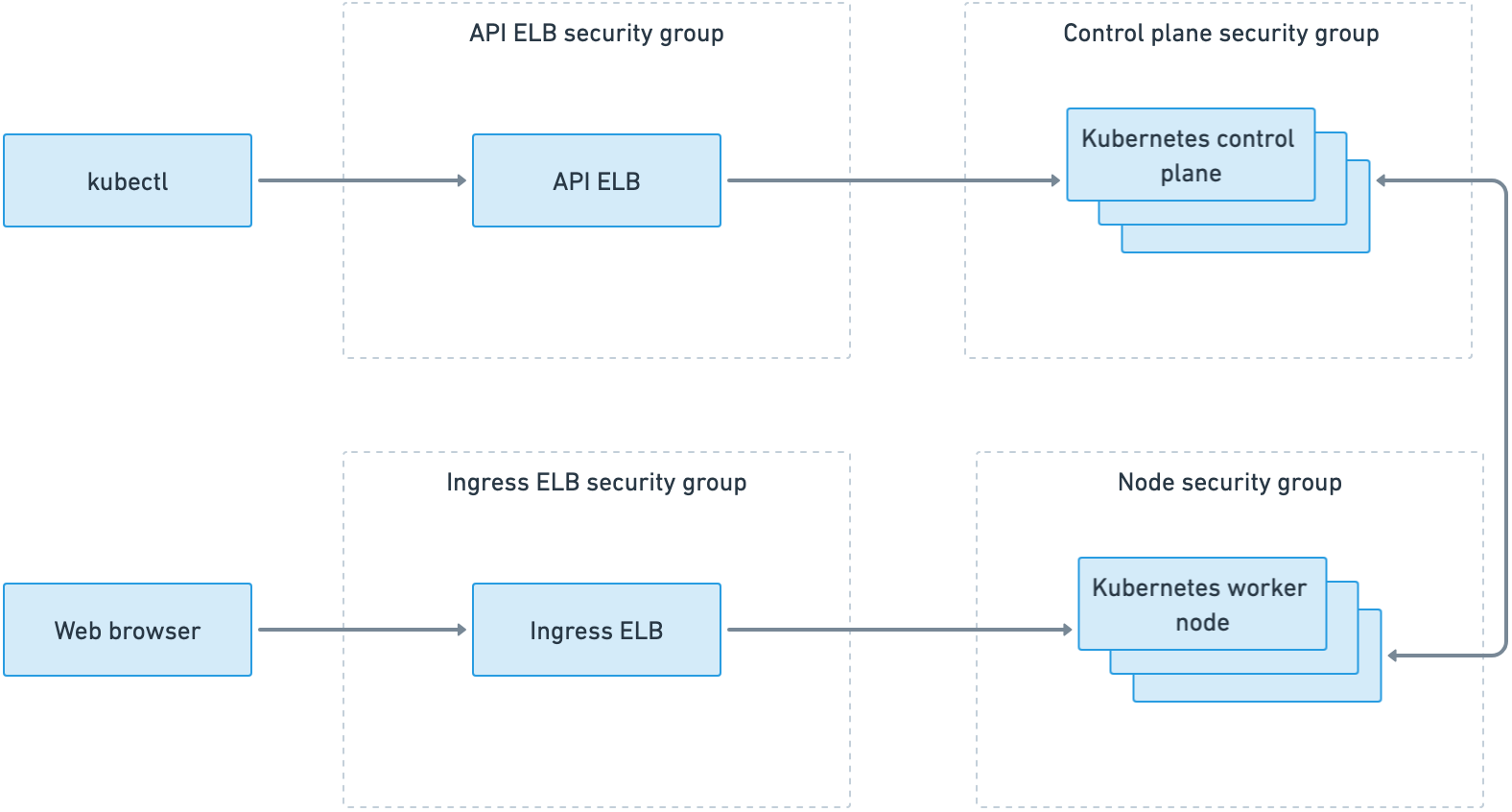
Kubernetes clusters can be configured in a variety of different ways. One method is to use the Kubernetes Operations (kOps) tool to configure Kubernetes on AWS.
In the diagram below, there are two AWS Elastic Load Balancers (ELBs), each with its own AWS security group:
-
One AWS ELB that fronts the Kubernetes control plane and provides access to the Kubernetes API which is accessed, for example, by the kubectl command-line client.
-
One AWS ELB fronts the Kubernetes nodes and provides access to the containers that are running on the cluster. In the case of CloudBees CI, these are the operations center and managed controllers.
kOps network ports
In a kOps created Kubernetes cluster on AWS, security groups are used to control access to the Kubernetes control plane and nodes. You can see the four security groups created in the above diagram. These are the ports that are open for each security group:
API ELB security group
-
HTTP from anywhere
-
TCP 443 from anywhere
Ingress ELB security group
-
HTTP from anywhere
-
ICMP (fragmentation required, DF flag set) from anywhere
-
TCP 443 from anywhere
Master security group
-
SSH from anywhere
-
HTTP from anywhere
-
All from the masters security group
-
Allows from the API ELB security group:
-
HTTP
-
TCP 443
-
TCP 4003-65536
-
-
Allows from the node security group:
-
TCP 1-2379
-
TCP 2382-4000
-
UDP 1-65536
-
Node security group
-
All from the node security group
-
All from the masters security group
-
All from the Ingress ELB security group
Ingress TLS termination
Ingress TLS termination should be used to ensure that network communication to the CloudBees CI UI is encrypted from end-to-end.
To ensure that your web browser to CloudBees CI communication is encrypted end-to-end, you must change the Kubernetes Ingress used by CloudBees CI to use your TLS certificates, thereby making it the termination point for TLS.
| This information provides a general overview of the changes you must make, but the definitive guide to set this up is in the Kubernetes Ingress TLS documentation. |
Store your TLS certificates in a Kubernetes secret
To make your TLS certificates available to Kubernetes, use the Kubernetes kubectl command-line tool to create a Kubernetes secret.
For example, if your certificates are in /etc/mycerts, issue this command to create a secret named my-certs:
kubectl create secret tls my-certs \ --cert=/etc/mycerts/domain.crt --key=/etc/mycerts/privkey.pem
For more information, refer to the definitive guide to secrets in the Kubernetes Secrets documentation.
Change the two CloudBees CI Ingresses to be the TLS termination point
Configure the CloudBees CI Helm values to use your TLS certificate via the OperationsCenter.Ingress.tls.Enable, OperationsCenter.Ingress.tls.SecretName Helm values, using my-certs as the SecretName. Refer to the following example:
OperationsCenter: Ingress: tls: # OperationsCenter.Ingress.tls.Enable -- Set this to true in order to enable TLS on the ingress record Enable: true # OperationsCenter.Ingress.tls.SecretName -- The name of the secret containing the certificate # and private key to terminate TLS for the ingress SecretName: my-certs
Domain name change
-
Stop all managed controllers/team controllers from the operations center dashboard. This can be achieved either automatically with a cluster operation or manually using .
-
Use one of the following options to modify the hostname in
ingress/cjocandcm/cjoc-configure-jenkins-groovyand add the new domain name:-
Change the hostname values in the
cloudbees-core.ymlfile. -
Edit the operations center ingress resource and modify the domain name.
$ kubectl edit ingress/cjocModify the operations center configuration map to change the operations center URL.
$ kubectl edit cm/cjoc-configure-jenkins-groovy
-
-
Delete the operations center pod and wait until it is terminated.
$ kubectl delete pod/cjoc -
Verify that has been properly updated. If it has not been updated, select the new domain and then select Save.
-
Start all managed controllers/team controllers from the operations center dashboard. This can be achieved either automatically with a cluster operation or manually using .
The new domain name must appear in all of those resources:
$ kubectl get statefulset/<master> -o=jsonpath='{.spec.template.spec.containers[?(@.name=="jenkins")].env}' $ kubectl get cm/cjoc-configure-jenkins-groovy -o json $ kubectl get ingress -o wide
The domain name must be identical to what is used in the browser; otherwise, a default backend - 404 error is returned.
|
Configuring persistent storage
For persistence of operations center and managed controller data, CloudBees CI must be able to dynamically provision persistent storage.
When deployed, the system provisions storage for the operations center’s $JENKINS_HOME directory and whenever a new managed controller is provisioned, the operations center provisions storage for that controller’s $JENKINS_HOME.
On Kubernetes, dynamic provisioning of storage is accomplished by creating a Persistent Volume Claim (PVC). The PVC uses a storage class to coordinate with a storage provisioner to provision that storage and make it available to CloudBees CI.
Refer to the next section to set up a storage class for your environment, if applicable.
|
A detailed explanation of Kubernetes storage concepts is beyond the scope of this document. For additional background information, refer to: |
Storage requirements
Since pipelines typically read and write many files during execution, CloudBees CI requires high-speed storage. When running CloudBees CI on EKS, CloudBees recommends using solid-state disk (SSD) storage.
| Although other disk types and AWS Elastic File System (Amazon EFS) are supported, the same level of performance cannot be guaranteed. |
By default, CloudBees CI uses the default storage class. You can provide an SSD-based storage class for CloudBees CI in the following ways:
-
Create a new SSD-based storage class and make it the default. This method is easier because you do not have to change the CloudBees CI configuration.
-
Create a new SSD-based storage class, and before you deploy, change the CloudBees CI configuration file to use the new storage class that you created.
Storage class considerations for multiple availability zones
For multi-zone environments, the volumeBindingMode attribute (supported since Kubernetes version 1.12) must be set to WaitForFirstConsumer; otherwise, volumes may be provisioned in a zone where the pod that requests it cannot be deployed.
This field is immutable.
Therefore, if it is not already set, a new storage class must be created.
| You can also use Amazon EFS to address the availability zones within a single region. |
Check the storage class configuration
After you create your Kubernetes cluster, retrieve the storage classes.
If the default storage class is not gp2, then you are not using SSD storage, and you must create a new SSD-based storage class.
$ kubectl get storageclass NAME PROVISIONER AGE default (default) kubernetes.io/aws-ebs 14d
Create a new SSD-based storage class
To create a new SSD-based storage class, you must create a YAML file that specifies the class and then run a series of kubectl commands to create the class and make it the default.
For more information on all supported parameters, refer to Kubernetes AWS storage class.
Create a gp2-storage.yaml file with the following content for gp2 type with encryption enabled:
kind: StorageClass apiVersion: storage.k8s.io/v1 metadata: name: gp2 provisioner: kubernetes.io/aws-ebs # Uncomment the following for multi zone clusters # volumeBindingMode: WaitForFirstConsumer parameters: type: gp2 encrypted: "true"
Create the storage class:
$ kubectl create -f gp2-storage.yaml
Make the SSD-based storage class the default
Configure your cluster and CloudBees CI to use your new storage class as the default:
$ kubectl patch storageclass gp2 -p '{"metadata": {"annotations":{"storageclass.kubernetes.io/is-default-class":"true"}}}' $ kubectl patch storageclass default -p '{"metadata": {"annotations":{"storageclass.kubernetes.io/is-default-class":"false"}}}'
Retrieve the storage classes, and your new storage class should now be the default:
$ kubectl get sc NAME PROVISIONER AGE gp2 (default) kubernetes.io/aws-ebs 1d default kubernetes.io/aws-ebs 14d
Enable storage encryption
Storage encryption should be used to ensure that all CloudBees CI data is encrypted at rest. If you want to set up this, you must configure storage encryption in your Kubernetes cluster before you install CloudBees CI.
This is done by configuring Kubernetes to use a default Kubernetes Storage Class that implements encryption. Refer the Kubernetes documentation for Storage Classes and your cloud provider’s documentation for more information about the available Storage Classes and how to configure them.
Configuring AWS EBS Encryption
To enable AWS encryption you must create a new Storage Class that uses the kubernetes.io/aws-ebs provisioner, enable encryption in that Storage class and then set it as the default Storage Class for your cluster.
The instructions below explain one way to this. You should refer to the Kubernetes documentation for the complete details of the AWS Storage Class.
Examine the default storage class
First, examine the existing Storage Class configuration of your cluster.
$ kubectl get storageclass NAME PROVISIONER AGE default kubernetes.io/aws-ebs 14d gp2 (default) kubernetes.io/aws-ebs 1d
You should look at the existing storage class to make sure it does not already use encryption, and to verify the name of the is-default-class annotation. The official documentation says the name should be storageclass.kubernetes.io/is-default-class but as you can see below, the name used in this particular cluster is storageclass.beta.kubernetes.io/is-default-class:
$ kubectl get storageclass gp2 -o yaml apiVersion: storage.k8s.io/v1 kind: StorageClass metadata: annotations: storageclass.beta.kubernetes.io/is-default-class: "true" creationTimestamp: 2018-02-13T21:37:05Z labels: k8s-addon: storage-aws.addons.k8s.io name: gp2 resourceVersion: "1823083" selfLink: /apis/storage.k8s.io/v1/storageclasses/gp2 uid: 0959b194-1106-11e8-b6ad-0ea2187dbbe6 parameters: type: gp2 provisioner: kubernetes.io/aws-ebs # Uncomment the following for multi zone clusters # volumeBindingMode: WaitForFirstConsumer reclaimPolicy: Delete
Create a new encrypted Storage Class
Create a new storage class in a YAML file with contents like the below. Pick a new name; below encrypted-gp2 is used. And note that there is a new parameter encrypted: true.
If you want to specify the keys to be used to encrypt the EBS volumes created by Kubernetes for CloudBees CI, then make sure to also specify the kmsKeyId, which, according to the documentation is "the full Amazon Resource Name of the key to use when encrypting the volume. If none is supplied but encrypted is true, a key is generated by AWS. See AWS docs for valid ARN value."
Here is an example Storage Class definition that specifies encryption:
apiVersion: storage.k8s.io/v1 kind: StorageClass metadata: labels: k8s-addon: storage-aws.addons.k8s.io name: encrypted-gp2 parameters: type: gp2 encrypted: "true" provisioner: kubernetes.io/aws-ebs # Uncomment the following for multi zone clusters # volumeBindingMode: WaitForFirstConsumer reclaimPolicy: Delete
Save your Storage Class to a file named, for example, sc-new.yml.
Next, use kubectl to create that storage class.
$ kubectl create -f sc-new.yml storageclass "encrypted-gp2" created
Look at the existing storage classes again and you should see the new one:
$ kubectl get storageclass NAME PROVISIONER AGE default kubernetes.io/aws-ebs 14d encrypted-gp2 kubernetes.io/aws-ebs 13s gp2 (default) kubernetes.io/aws-ebs 14d
Set your new Storage Class as the default
Refer to the Kubernetes documentation for changing the default storage class. In summary, you need to mark the existing default as not-default, then mark your new storage class as default. Below are the steps.
Mark the existing default storage class as not default, and be sure to use the right annotation name that we saw above:
kubectl patch storageclass gp2 \ -p '{"metadata": {"annotations":{"storageclass.beta.kubernetes.io/is-default-class":"false"}}}'
Mark the new encrypted storage class as the default:
kubectl patch storageclass encrypted-gp2 \ -p '{"metadata": {"annotations":{"storageclass.kubernetes.io/is-default-class":"true"}}}'
Now, verify that the new encrypted storage class is the default:
$ kubectl get storageclass NAME PROVISIONER AGE default kubernetes.io/aws-ebs 14d encrypted-gp2 (default) kubernetes.io/aws-ebs 50m gp2 kubernetes.io/aws-ebs 14d
Now you can proceed to deploy CloudBees CI. With the encrypted storage class in place, all EBS volumes created by CloudBees CI will be encrypted.
Integrate single sign-on
Once your CloudBees CI cluster is up and running, you can integrate it with a SAML-based single sign-on (SSO) system and configure Role Based Authentication Controls (RBAC). This is done by installing the Jenkins SAML plugin, configuring it to communicate with your IDP, and then configuring your IDP to communicate with CloudBees CI.
Prerequisites for this task
Before you set up SAML-based SSO and RBAC, you must:
| When you make changes to the security configuration, you may lock yourself out of the system. If this happens, you can recover by following the instructions in the How do I log in into Jenkins after I’ve logged myself out CloudBees Knowledge Base article. |
Install the SAML plugin
To install the SAML plugin on the operations center:
-
Sign in to the operations center and select
-
Enter
SAMLin the search box. -
Select the SAML plugin.
-
Select Download now and install after restart
-
Select Restart Jenkins when installation is complete and no jobs are running.
You do not need to install the plugin on managed controllers; you only need to install the plugin to the operations center.
Enable and configure SAML authentication
-
Sign in to the operations center and select .
-
Select Enable security and confirm there is a SAML 2.0 option in the Security Realm setting.
If the SAML 2.0 option is not present, then the Jenkins SAML plugin is not installed, and you need to install the SAML plugin. -
Read and carefully follow the Jenkins SAML plugin instructions.
-
Enter the IDP Metadata (XML data) and specify the attribute names that your IDP uses for username, email, and group membership.
-
When you are ready, select Save to store the new security settings.
Export service provider metadata to your IDP
After you save your security settings, the operations center reports your service provider metadata (XML data). You must copy this data and give it to your IDP administrator, who will add it to the IDP configuration.
You can find the service provider metadata by following the link on the Security page at the end of the SAML section. The link looks similar to the following:
Service Provider Metadata which may be required to configure your Identity Provider (based on last saved settings).
Sign in to the operations center and set up RBAC
-
Once your IDP administrator confirms that your IDP metadata has been added to the IDP, sign in to the operations center.
-
Enable and configure RBAC. For more information, refer to Restrict access and delegate administration with Role-Based Access Control.
Cloud-ready artifact manager for AWS
Jenkins has historically provided multiple ways to save build products, otherwise known as artifacts.
Some plugins permit you to upload artifact files to repository managers like Artifactory plugin and Nexus Artifact Uploader plugin. Other plugins send artifacts to remote shared filesystems, such as Publish Over FTP plugin, Publish Over CIFS plugin, and Publish Over SSH plugin. Jenkins itself stores artifact files in the Jenkins home filesystem. In 2012, CloudBees released the Fast Archiver Plugin, which optimizes the default artifact transmission but uses the same storage location.
Unfortunately, a number of these solutions are not cloud-ready, and it is awkward and difficult to use them with CloudBees CI. Some solutions, such as the S3 publisher plugin are well-suited for use in a cloud environment, but require special build steps within Pipelines.
CloudBees is developing a series of cloud-ready artifact manager plugins. The first of these is the Artifact Manager on S3 plugin. This plugin permits you to archive artifacts in an S3 Bucket, where there is less need to be concerned about the disk space used by artifacts.
Configure Artifact Manager on an Amazon S3 bucket
To configure Artifact Manager on an Amazon S3 bucket:
-
Navigate to .
-
In the Artifact Management for Builds section, select the Amazon S3 cloud provider.

-
Return to to configure your AWS credentials for access to the Amazon S3 bucket.
-
For your AWS credentials, use the IAM Profile configured for the Jenkins instance, or configure a regular key or secret AWS credential in Jenkins.
Your AWS account must have permissions to access the Amazon S3 bucket and must be able to list, get, and put objects in the Amazon S3 bucket. 
-
Save or apply the credentials configuration, and move on to configure your Amazon S3 bucket settings.
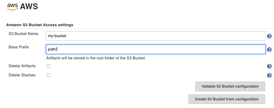
-
CloudBees recommends validating your configuration. If the validation succeeds, you’ve completed the configuration for Artifact Manager on S3.

For more details about Artifact Manager for S3, refer to Artifact Manager on S3 plugin.
Uploading and downloading artifacts
The Artifact Manager on S3 plugin is compatible with both Pipeline and FreeStyle jobs.
| To archive, unarchive, stash or un-stash, use the default Pipeline steps. |
FreeStyle jobs
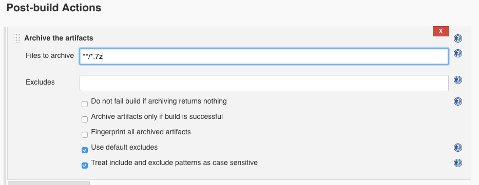
For FreeStyle jobs, use an Archive the Artifacts post-build action to store your artifacts in the Amazon S3 Bucket:
To copy artifacts between projects:
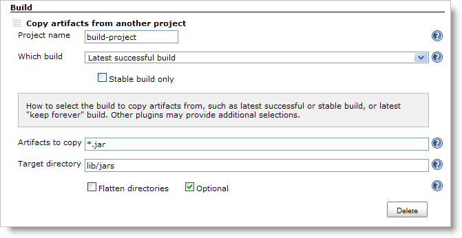
-
Make sure the Copy Artifact plugin is installed.
-
Use a build step to copy artifacts from the other project.
Pipeline jobs
For Pipeline jobs, use an archiveArtifacts step to archive artifacts into the Amazon S3 bucket:
node() { //you build stuff //... stage('Archive') { archiveArtifacts "my-artifacts-pattern/*" } }
To retrieve artifacts that were previously saved in the same build, use an unarchive step that retrieves the artifacts from the Amazon S3 bucket.
Set the mapping parameter to a list of pairs of source-filename and destination-filename:
node() { //you build stuff //... stage('Unarchive') { unarchive mapping: ["my-artifacts-pattern/": '.'] } }
To save a set of files for use later in the same build (generally on another node/workspace), use a stash step to store those files on the Amazon S3 bucket:
node() { //you build stuff //... stash name: 'stuff', includes: '*' }
To retrieve files saved with a stash step, use an unstash step, which retrieves previously stashed files from the Amazon S3 bucket and copies them to the local workspace:
node() { //you build stuff //... unstash 'stuff' }
To copy artifacts between projects:
-
Make sure the Copy Artifact plugin is installed.
-
Use a
copyArtifactsstep to copy artifacts from the other project:node(){ //you build stuff //... copyArtifacts(projectName: 'downstream', selector: specific("${built.number}")) }
Security
The Artifact Manager on S3 plugin manages security using Jenkins permissions. This means that unless users or jobs have permission to read the job in Jenkins, the user or job cannot retrieve the download URL.
Download URLs are temporary URLs linked to the Amazon S3 bucket, with a duration of one hour. Once that hour has expired, you must request a new temporary URL to download the artifact.
Agents use HTTPS (in the form of https://my-bucket.s3.xx-xxxx-x.amazonaws.com/*) and temporary URLs to archive, unarchive, stash, unstash and copy artifacts.
Agents do not have access to either the AWS credentials or the whole Amazon S3 bucket, and are limited to get and put operations.
Performance
A major distinction between the Artifact Manager for S3 plugin and other plugins is in the load on the controller and the responsiveness of the controller-agent network connection. Every upload/download action is executed by the agent, which means that the controller spends only the time necessary to generate the temporary URL; the remainder of the time is allocated to the agent.
The performance tests detailed below compare the CloudBees Fast Archiving plugin and the Artifact Manager on S3 plugin.
Performance tests were executed in a Jenkins 2.121 environment running on Amazon EC2, with $JENKINS_HOME configured on an Amazon EBS volume.
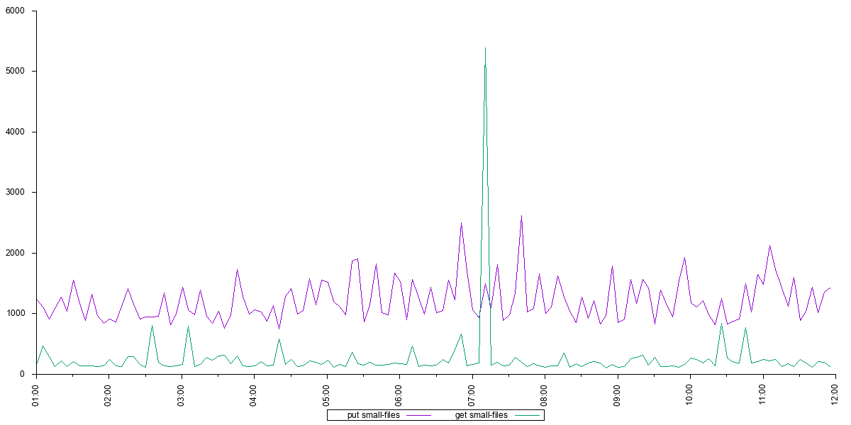
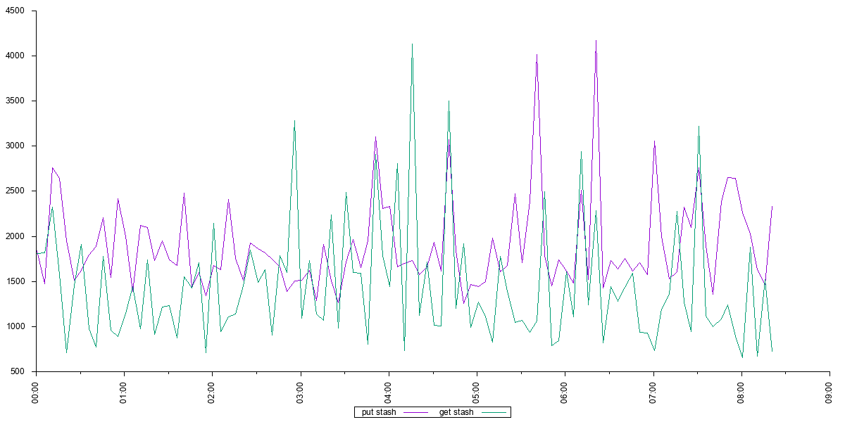
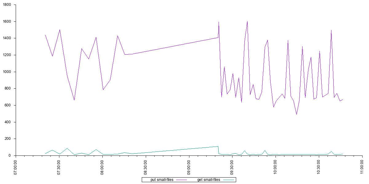
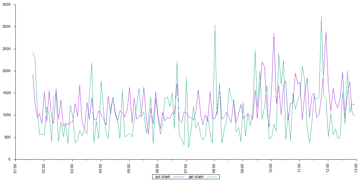
Three different kinds of tests were executed from the GitHub repository, with samples taken after the tests had been running for one hour:
-
Archive/unarchive big files: Store a 1GB file and restore it from the artifact management system.
-
Archive/unarchive small files: Store 100 small files and restore them from the artifact management system. Small files are approximately 10 bytes in size, with 100 files stored and times averaged.
-
Stash/unstash on a pipeline: Execute stash and unstash steps. The Fast Archive plugin stash/unstash operations used the default stash/unstash implementation.
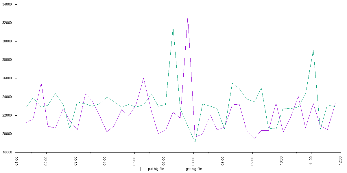
As can be seen from the results, the Artifact Manager on S3 plugin provides a measurable performance improvement on both big and small files, with the improvement measured in minutes for big files and in seconds for small files.
Artifact Manager on S3 plugin performance
Artifact Manager on S3 plugin
Big files
|
||
Time in milliseconds |
Archive |
Unarchive |
Max |
48,578.00 |
29,899.00 |
Min |
17,773.00 |
20,388.00 |
Avg |
20,969.49 |
22,670.67 |
CloudBees Fast Archiving plugin performance
CloudBees Fast Archiving plugin
Big files
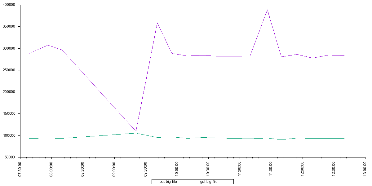
|
||
Time in milliseconds |
Archive |
Unarchive |
Max |
358,988.00 |
105,615.00 |
Min |
110,068.00 |
93,193.00 |
Avg |
277,642.22 |
95,771.78 |
